ATTiny85 PWM Solar Charge Controller
Posted on 10/12/2015 by Adam
After receiving Julian’s comment on my first Arduino solar charge controller Youtube video I’ve been thinking of ways to reduce the power consumption, but after a fair bit of reading (and a bit of guessing) I’ve been able to come up with a working prototype. In the video below I look at the code, how to program ATTinys and the trade offs that come with reducing power consumption.
Layout Diagram:
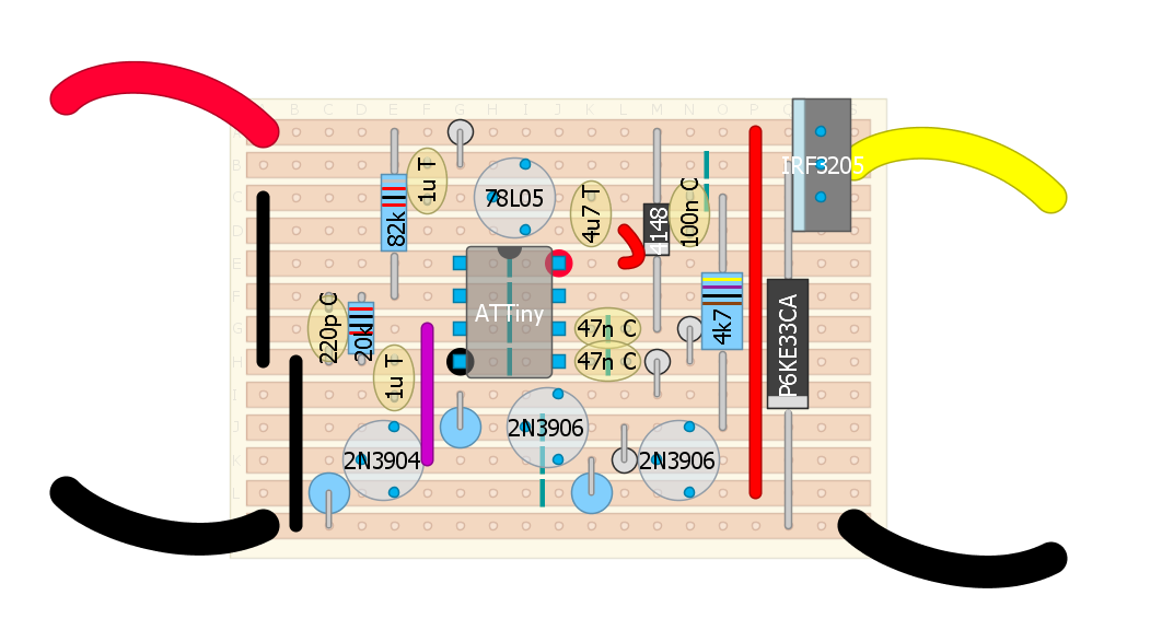
Parts List (Ebay affiliate links)
1x Arduino Nano Clone: https://goo.gl/lgAAdC
1x IRF3205 Mosfet: https://goo.gl/eepYsc
1x 2N3904 NPN Transistor: https://goo.gl/dbsFjG
2x 2N3906 PNP Transistor: https://goo.gl/Ju6JQ7
4x 1N4148 Diode: https://goo.gl/Dz58VA
1x P6KE33CA TVS Diode: https://goo.gl/4JNAxH
1x 90SQ035 Schottky Diode 9A/35v (or similar): https://goo.gl/c9W9Mn
2x 47nF 50v Ceramic Capacitor: https://goo.gl/XXsRcx
1x 1uF 50v Ceramic Capacitor: https://goo.gl/d6S8Vg
1x 220pF 100v Ceramic Capacitor: https://goo.gl/H3jQpw
1x 470nF 10v Tantalum Capacitor: https://goo.gl/32leQJ
2x 1uF 35v Tantalum Capacitor: https://goo.gl/zpBuUy
1x 82k 1% 0.25w Resistor: https://goo.gl/yvhjPA
1x 20K 1% 0.25w Resistor: https://goo.gl/1hdms1
3x 220K 0.5w Resistor: https://goo.gl/MQYTwH
1x 4.7K 0.5w Resistor: https://goo.gl/phf1uD
1x Verobaord: https://goo.gl/Jefc5v
Sketch:
[code]
//PWM Solar charge controller using Julian Iletts design and code (http://256.uk) but adapted to work on the ATTiny25/45/85 by Adam Welch (.)
const int setPoint = 13.5 * 20 / (20+82) * 1024 / 5 ;
int measurement = 0;
int pulseWidth = 0;
int difference = 0;
int stepSize = 0;
void setup() {
TCCR0A = 2<<COM0A0 | 3<<COM0B0 | 3<<WGM00; // Timer 0 Control Register A - Set None Inverting Mode, Set Inverting Mode, Enable Fast PWM
TCCR0B = 0<<WGM02 | 1<<CS00; // Timer 0 Control Register B - Enable Fast PWM, No Prescaler
TCCR1 = 0<<PWM1A | 0<<COM1A0 | 1<<CS10; // Timer 1 Control Register - Prevent timer using pin OC1A, again prevents use, No Prescaler
GTCCR = 1<<PWM1B | 2<<COM1B0; // General Control Register for Timer 1 - Enable use of pin OC1B, None inverting mode.
analogWrite(0, 117); //ATTiny85 Leg 5 // OC0A
analogWrite(1, 137); //ATTiny85 Leg 3 // OC1B
}
void loop() {
measurement = analogRead(A3); //ATTiny85 Leg 3
difference = abs(setPoint - measurement);
stepSize = difference;
if (measurement &lt; setPoint)
{
pulseWidth += stepSize;
if (pulseWidth &gt; 255) pulseWidth = 255;
}
else if (measurement &gt; setPoint)
{
pulseWidth -= stepSize;
if (pulseWidth &lt; 0) pulseWidth = 0;
}
//Serial.println(pulseWidth);
analogWrite(4, pulseWidth); //ATTiny Leg 2
delay(10);
[/code]