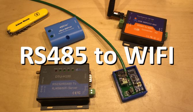
Build Your Own RS485 to Wifi Adapter for EPEver Solar Charge Controllers
Posted on 29/12/2017 by Adam
Many EPEver solar charge controllers have an RS485 communication port on them so you can connect a PC or Android device and read it’s statistics or update the settings.
Although EPEver have themselves developed a wifi adapter for the solar charge controllers which support RS485 it has some flaws which makes it less useful than it could have been. Recent versions of the software have prevented the EPEver eBox Wifi-01 from connecting to normal wifi networks entirely although it had been implemented in early firmware versions.
Other commercial RS485 to wifi adapters do exist but typically they tend to cost more than the eBox and draw more current – not ideal for a solar charge controller.
Colin Hickey decided that there must be another option and after much research and a few dead ends found the open source ESPLink software by jeelabs. This allows the popular ESP8266 (Ebay affiliate link)�to easily become a wifi to serial bridge. Now he just needed a serial to RS485 solution which came in the form of the XY-017 TTL to RS485 module (Ebay affiliate link) which is widely available on eBay.
Colin talks about the journey and his solution for the EPEver solar charge controllers in this series of videos.
DIY RS485 wifi Adaptor Playlist
After dabbling with this design using perfboard, Adam Welch thought it might be an opportunity to take his first plunge into designing a custom PCB and have some boards manufactured to allow easier connection of the components, and to his surprise they seem to have worked quite well!
Colin Hickey is selling completed built and flashed units ready to plug in and connect to your wifi network. You can buy them soon.
Components required:
RS485 to ESP8266 PCB: http://admw.uk/kh (Zipped Gerber File)
ESP8266 ESP-01: https://goo.gl/HGJZL7 (Ebay affiliate link)
XY-017 RS485 to TTL Module: https://goo.gl/nEFZsc (Ebay affiliate link)
RJ45 Network Cable: https://goo.gl/2UAR78 (Ebay affiliate link)
Pin Header: https://goo.gl/gNxgzb (Ebay affiliate link)
Assembly is very simple – just follow the silkscreen on the PCB and the following colour code for the network cable. (The assumption is you’re re-purposing a standard network cable)
Orange Solid – Vcc (V)
Green Stripe – RS485 B (B)
Green Solid – RS485 A (A)
Brown Solid – Ground (G)
The other four wires may be cut short and isolated.
Flashing the ESP with ESPLink firmware is quite straight forward. Download ESPLink (I suggest using version 2.2.3) and extract the contents of the tar file to your hard drive (7zip is a good option to untar). Download the NodeMCU Flasher program and configure it as shown below.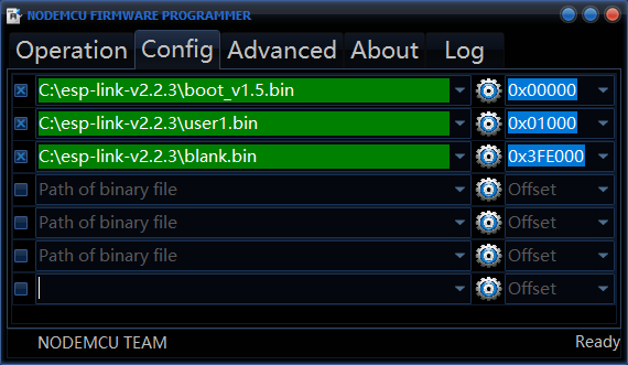
Finally plug in your ESP8266 into your programmer and plug it into your PC. Choose the correct COM port on the Operation tab and click Flash.